In recent years, electronic circuit design has seen an increase in the number of multifunctional ICs, and the number of pins and package shapes have been more diverse as ICs have become more powerful and compact. IC sockets therefore attract attention, as they allow ICs to be inserted into boards without soldering, making replacement and maintenance easier.
In this article, we will discuss the key points when selecting IC sockets, focusing on “package shape,” “pin shape,” and “number of pins,” and hope that it will be helpful to those who have trouble selecting IC sockets or who want to start circuit design.
About IC Socket

IC socket is a component that allows ICs to be mounted on a board in a removable form. Normally, when ICs are mounted on boards, Soldering secure them. However, soldered ICs cannot be easily replaced, making repairs difficult in the event of failure or upgrades. On the other hand, when mounted via IC sockets, ICs can be removed and inserted easily, providing the following advantages
- Easy replacement and maintenance:When an IC fails, it can be simply removed from the socket and replaced, reducing repair costs.
- Board protection:Repeated soldering may damage board patterns, but the use of sockets reduces this risk.
- Improved efficiency in prototyping and development:When evaluating a new IC, it can be easily replaced and tested, speeding up prototype development.
On the other hand, the use of IC sockets increases component costs and there is also a non-zero risk of contact defects in the sockets themselves. Nevertheless, they offer significant advantages, especially in the maintenance and prototyping phases, making them indispensable components in electronic circuit design.
IC Sockets by Package Shape
ICs come in a variety of package shapes. Since sockets also need to have a shape and structure corresponding to each package, let’s first look at the types of sockets for each package shape.
Sockets for DIP(Dual In-line Package)
DIP refers to the shape in which the pins of an IC are arranged in two rows along the long side. Although it is a legacy package, it is still often used in general-purpose logic ICs and some microcontrollers, and is a familiar presence in electronic construction and experimentation.
- Typical Characteristics
- The pitch between pins is typically 2.54 mm (0.1 inch).
- Sockets with a variety of pin counts, such as 8-pin, 14-pin, 16-pin, 20-pin, 28-pin, and 40-pin, are commercially available to match the shape of the IC.
- Socket shape
- Open frame type:The center of the socket is hollowed out, making it easy to insert and remove ICs and also providing advantages in heat dissipation.
- Closed frame type:Consists of a square frame that holds the IC firmly in place.
- Merits and Demerits
- Merits:The socket itself is relatively inexpensive and smooth to insert and remove. Design is easy if the height can be secured on the board.
- Demerits:The mounting area is larger than that of other packages and may not be suitable for recent high-density mounting.
Sockets for QFP(Quad Flat Package)
QFP is a package with flat leads extending to the four sides of the IC. Because of the large number of pins and miniaturized chips, they are generally mounted by soldering. However, sockets for QFPs are used when it is necessary to easily attach and detach QFP packages for evaluation or prototyping purposes.
- Typical Characteristics
- With leads on all four sides, it is not unusual for the number of pins to range from 20 to 100 or more.
- For products with a fine lead pitch (0.5 mm, 0.4 mm, etc.), the sockets also require high precision, and the product price tends to be high.
- Merits and Demerits
- Merits: Useful for frequent IC replacement during development and evaluation stages. Easier than solder rework.
- Demerits: Since the sockets are specially designed, installation and alignment are severe. The price is also higher than that for DIP.
Sockets for QFN(Quad Flat No-leads)
QFN is a package with lands on the sides and back of the IC, instead of having the leads on the outside as in QFP. It can mount thinner and smaller ICs, and is widely used in mobile devices and IoT devices. However, it is a package in which the leads are difficult to see during soldering mounting, making manual soldering and inspection difficult.
- Features of Socket
- Fine contact pins are placed inside the socket and are crimped to the back or side land of the IC.
- Many types use a special pawl or sliding mechanism to secure the IC.
- Merits and Demerits
- Merits: QFN package ICs can be easily replaced on evaluation boards or in the prototype stage.
- Demerits: The socket structure is complex and the price is a little high, though not as high as BGA. Suitable for evaluation rather than mass production.
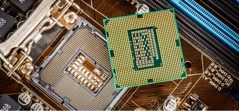
Sockets for BGA(Ball Grid Array)
BGA is a package in which a large number of solder balls are arranged in a grid pattern on the backside of the IC. It is a common shape for high-performance chips such as CPUs and GPUs due to its high pin count and high density. Reflow soldering is commonly used for normal board mounting, but BGA mounting is difficult to rework because the leads are not visible from the outside. Also, the number of solder balls is very large, and mounting accuracy is strictly required.
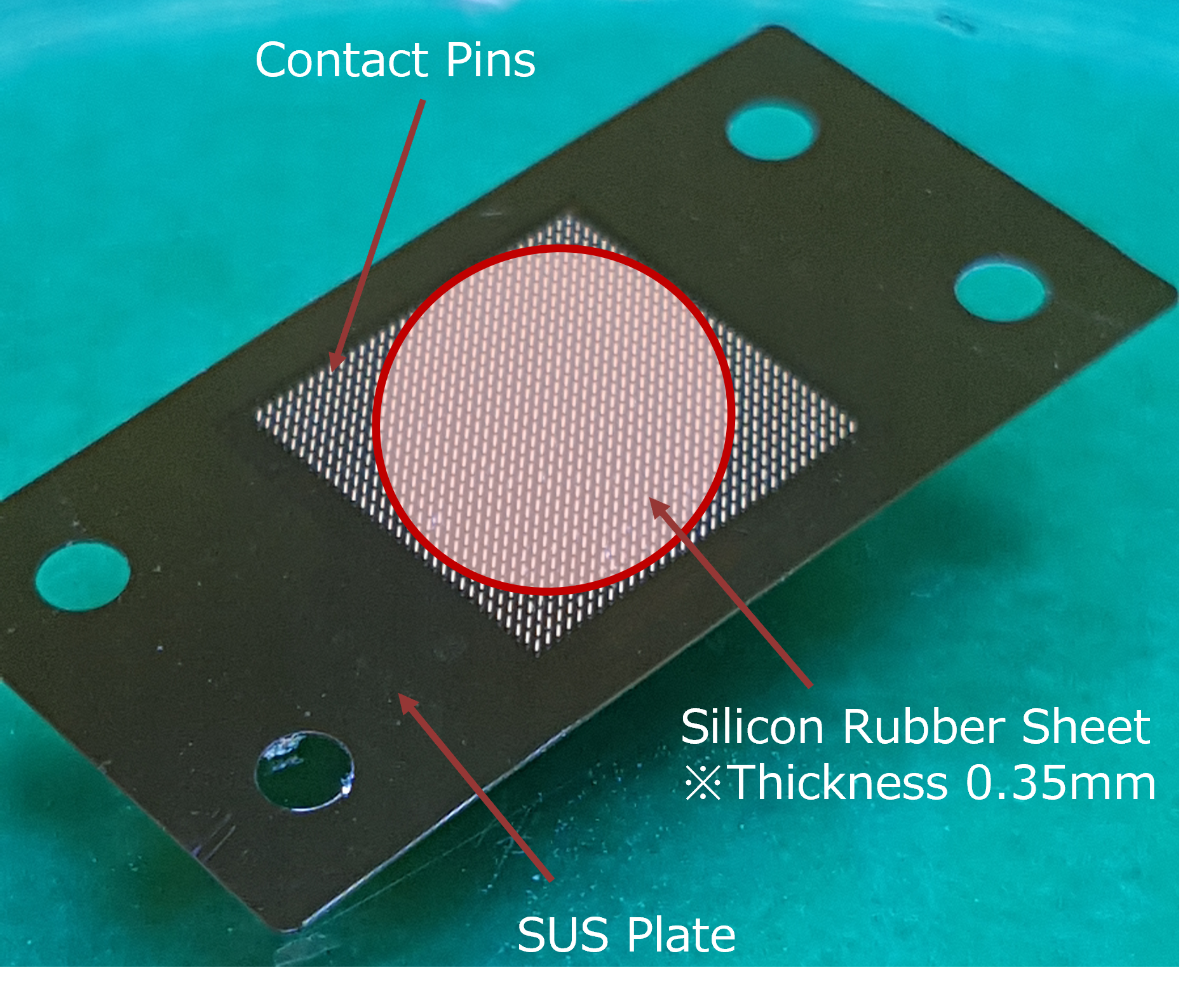
- Features of Socket
- A structure in which dedicated contact pins correspond to the balls on the backside of the IC and electrically contact each one of them.
- The sockets themselves are in the high price range because of the high precision required for alignment during installation.
- Merits and Demerits
- Merits: Facilitates prototyping and evaluation of BGA chips and allows repeated attachment and removal.
- Demerits: Expensive, have limited availability, and often require specialized jigs for implementation.
Other package shapes
In addition to the 4 types (DIP / QFP / QFN / BGA) introduced above, there are various other shapes of IC packages. Sockets corresponding to them are also commercially available, so selection must be made in accordance with the application and required specifications.
- Sockets for PLCC(Plastic Leaded Chip Carrier):Shaped with leads on the side, the PLCC socket is mounted to fit the IC. A special extractor is used for removal.
- Sockets for PGA(Pin Grid Array):Used to be common in PC CPUs. The pins are arranged in a grid pattern, and the socket with ZIF (Zero Insertion Force) mechanism is used for connection and disconnection.
- Sockets for LGA(Land Grid Array):A structure in which the ball portion of the BGA is like a land, and the land is held in place by contact pins on the board side. Popular among CPU for PC in these days.
- Sockets for SOIC/SOP:A type of small horizontal package held by a socket, which requires a smaller pitch than a DIP socket.
Difference in pin shape (socket side)
When selecting an IC socket, attention should be paid not only to the corresponding IC package, but also to the shape and quality of the pins (contacts) on the socket side. Broadly speaking, the following two types of pin shapes are typical.
Round pin (machine pin) type
- Features
- Also called a turned pin, it uses a precision-machined cylindrical metal sleeve to make contact with the pins of the IC.
- The contact surface is circumferential, making it easy to obtain stable contact pressure.
- Merits
- High contact reliability and excellent durability make it suitable for applications that require repeated insertion and removal and environments that demand high reliability.
- The product is strong and does not easily distort pins or cause contact failures, even after long-term use.
- Demerits
- Higher manufacturing costs tend to lead to higher prices than those of flat pin types.
Flat pin (stamp pin) type
- Features
- It is made by pressing (punching) and bending a metal sheet, resulting in a square or plate-shaped cross section.
- It is elastic in the longitudinal direction and makes contact with the IC leads.
- Merits
- Production costs are low, making it easy to adopt for mass production applications.
- Due to its low-profile structure, DIP sockets, etc., it is easy to reduce the overall height.
- Demerits
- Contact area is not as large as that of machine pins, and contact failure is likely to occur when repeated insertion/removal is frequent or in harsh environments.
The key to choosing either pin shape is the balance between cost and the required reliability. If ICs are frequently inserted and removed for prototyping or evaluation, the round pin type is a safe choice, while the flat pin type is often chosen for mass production to keep costs down.
IC Sockets by Pin Count
ICs come in a wide variety of pin counts, from the 8 pins of a DIP to the thousands of pins of a BGA, with packages optimized for different applications and performance. Of course, IC sockets must also be selected in accordance with the number of pins.
For DIP sockets
DIP sockets are commercially available in a wide variety, such as 8-pin, 14-pin, 16-pin, 20-pin, 28-pin, and 40-pin. In most cases, they are available in standardized versions to match the pin counts of general-purpose logic ICs (74 series, 4000 series, etc.), operational amplifier ICs, microcontrollers, and other devices.
- Notes
- As sockets with more pins are larger in size, space allocation in the board layout must be considered.
- The thickness and the mounting height vary depending on whether the socket is open frame or closed frame, and whether the pin shape is round or flat.
For QFP / QFN / BGA sockets
QFP, QFN, and BGA are available in a wide range of pin counts, from small chips with as few as 20 pins to large ICs with several thousand pins. Sockets are also designed to accommodate various pin counts and pin pitches. Some sockets are general-purpose types with a wide range of support, while others are specialized sockets optimized for specific ICs.
- Notes
- The narrower the pitch, the more high-precision and expensive sockets are required.
- Since they are mainly for limited applications such as evaluation testing and prototyping, rather than for mounting in mass production, it may take time to obtain them.
For PGA sockets
Packages with a large number of pins arranged in a grid pattern, such as PGA, were widely used in CPUs for PCs in the past. The number of pins can reach 100 or more, and sockets equipped with ZIF levers and the like are the mainstream. In recent years, many CPUs have migrated to LGA and BGA, but PGA remains in some cases for industrial equipment and some embedded applications.
Other selection factors
When selecting an IC socket, pay attention not only to the package shape, pin shape, and pin count, but also to the following points.
With or without ZIF (Zero Insertion Force) mechanism
ZIF sockets are equipped with a lever or slide mechanism that requires very little force when inserting ICs into the socket. After the IC is set, the lever is lowered to secure it in place, minimizing the risk of damaging the pins.
- Merits
- Useful for evaluation boards that frequently insert and remove ICs.
- Reduces pin breakage and contact wear
- Notes
- Compared to general sockets, the component structure is more complex and the cost is higher.
- In terms of mounting area and height, it is necessary to secure space for the ZIF mechanism.
Socket height and frame structure
When mounting IC sockets, height limitations on the board, heat dissipation, and ease of IC removal must also be considered. If open frame or low type sockets are chosen, they can be made thin while ensuring ventilation. On the other hand, closed frame or high type sockets are easier to reliably protect ICs, but require more board space.
Contact material and plating specifications
Phosphor bronze or beryllium copper is used for the socket contacts, and gold or tin plating may be applied as a surface treatment.
- Gold plating: Suitable for situations requiring high reliability due to its resistance to oxidation and low contact resistance. Cost is high.
- Tin plating: Widely used in general applications, but requires appropriate storage and use environments to avoid oxidation risks.
Burn-in Socket
When performing long-time operation tests or high-temperature tests (burn-in tests) of ICs, we use “burn-in sockets” with excellent heat resistance and durability, instead of ordinary sockets. They are designed to resist contact failure and deformation even in high-temperature environments, and are indispensable for reliability tests.
IC sockets allow ICs to be mounted on boards without soldering, facilitating replacement and maintenance. In recent years, as ICs have become more powerful and compact, and the number of pins and package shapes have diversified, the requirements for sockets have also increased. Selecting the appropriate IC socket will lead to improved development efficiency and maintainability.
Test sockets adaptable to high-frequency, high-current and other challenges in next-generation semiconductors
MMS test socket developed by UPT is a revolutionary final test socket that responds to the evolution of semiconductor ICs. With the spread of 5G and AI, MMS meets the needs for semiconductor IC final test, which requires high frequency and high current capability. In addition, because it can handle smaller and narrower pitch semiconductors, MMS strongly supports the development, design, and manufacturing of next-generation semiconductors.
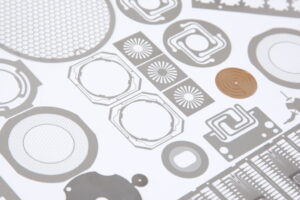
Micro Metal Socket®
The holes for socket mounting can be freely arranged.
Feature
Contact height: 0.45mm~
Contact pitch: 0.15mm~
High-speed transmission characteristics with ultra-short transmission line (67GHz@-1dB)
Load / displacement: 0.10N / 0.1mm
Capability
Supports high-speed transmission at 67GHz@-1dB
Rated current : 1A/contact (for contact length 0.45mm)
*We offer the best products in accordance with the dimensions of the object to be measured, terminal pitch, required load, etc.